
SETUP
1. Configure the switch (L2/L3) Cisco Switch
A. Create VLAN
#conf t
#vlan 635
#name PRE-QA
B. Assign IP Address for the created VLAN (This will be the gateway of VMs)
Note: On layer 3 Switch, there should be a routing configurations so that the switch knows where to route the traffic. In this case the default route via
ip default-gateway 10.63.0.253 GW
ip route 0.0.0.0 0.0.0.0 10.63.0.253
#show vlan
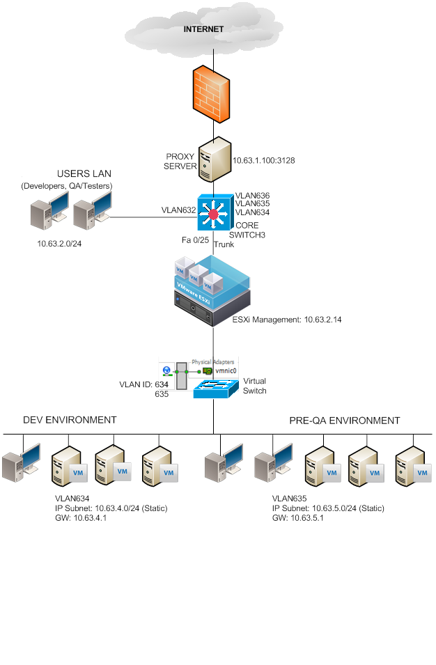
interface Vlan634
description DEV-ENVIRONMENT
ip address 10.63.4.1 255.255.255.0
!
interface Vlan635
description PRE-QA-ENVIRONMENT
ip address 10.63.5.1 255.255.255.0
!
C. Configure the port
#interface fast Ethernet X
#switchport trunk encapsulation dot1q
#switchport trunk allowed vlan [all];[vlanid]
#switchport mode trunk
#switchport nonegotiate
#no ip address
#no cdp enable
#spanning-tree portfast trunk
!
interface FastEthernet0/25
description PRE-QA-ESXi-HOST
switchport trunk encapsulation dot1q
switchport mode trunk
!
2. Configure ESXi Host Networking
A. Create Virtual Switch
Add Networking
Connection Type: Virtual Machine
Create a vSphere Standard switch (Choose the Physical NIC e.g. vmic1; this NIC should be connected on the switch configured as Trunk above.)
Network Label: VLAN635
VLAN ID: 635
B. Configure the vSwitch Properties
Load Balancing: Route based on IP Hash

C. Set the Network Adapter of the VM to use the VM Network for VLAN635

D. Assign IP on VM and test the connectivity, you can ping the Gateway now (VLAN IP Address)
IP: 10.63.5.X
NM: 255.255.255.0
GW: 10.63.5.1 (VLAN IP Address)
3. Create more VM Network
A. On ESXi Host, Networking
B. Go to Properties, Ports
C. Add
D. Virtual Machine
E. Network Label: VLAN636
VLANID: 636
Finished


VLAN Trunking VSwitch
Sample configuration of virtual switch VLAN tagging (VST Mode) (1004074)
Purpose
This article provides a sample network configuration for isolation and segmentation of virtual machine network traffic.
Resolution
To configure Virtual Switch (vSwitch) VLAN Tagging (VST) on an ESXi/ESX host:
1. Assign a VLAN to a portgroup(s). The supported VLAN range is 1-4094.
Reserved VLAN IDs:
VLAN ID 0 (zero) Disables VLAN tagging on port group (EST Mode)
VLAN ID 4095 Enables trunking on port group (VGT Mode)
2. Set the switch NIC teaming policy to Route based on originating virtual port ID (this is set by default).
To configure the physical switch settings:
1. Define ESXi/ESX VLANs on the physical switch.
2. Allow the proper range to the ESXi/ESX host.
3. Set the physical port connection between the ESXi/ESX host and the physical switch to TRUNK mode. ESXi/ESX only supports IEEE 802.1Q (dot1q) trunking.
Physical switch is set to TRUNK mode
dot1q encapsulation is enabled
Spanning-tree is set to portfast trunk (for example, port forwarding, skips other modes)
Define VLAN interface
Assign IP Range to VLAN interface
VLAN Routing – and VLAN IsolationCaution: Native VLAN ID on ESXi/ESX VST Mode is not supported. Do not assign a VLAN to a port group that is same as the native VLAN ID of the physical switch. Native VLAN packets are not tagged with the VLAN ID on the outgoing traffic toward the ESXi/ESX host. Therefore, if the ESXi/ESX host is set to VST mode, it drops the packets that are lacking a VLAN tag.
This sample is a supported Cisco Trunk Port configuration:
interface GigabitEthernet1/2
switchport (Set to layer 2 switching)
switchport trunk encapsulation dot1q (ESXi/ESX only supports dot1q, not ISL)
switchport trunk allowed vlan 10-100 (Allowed VLAN to ESXi/ESX. Ensure ESXi/ESX VLANs are allowed)
switchport mode trunk (Set to Trunk Mode)
switchport nonegotiate (DTP is not supported)
no ip address
no cdp enable (ESXi/ESX 3.5 or higher supports CDP)
spanning-tree portfast trunk (Allows the port to start forwarding packets immediately on linkup)
Note: For more information on configuring your physical network switch, contact your switch vendor.
To assign a VLAN to a port group, there must be a corresponding VLAN interface for each VLAN on a physical switch with a designated IP range.
For example:
interface Vlan200
ip address 10.10.100.1 255.255.255.0 (This IP can be used as VLAN 200 Gateway IP)
Note: When the VLAN ID is defined on the physical switch, it can be configured for ESX. If the IP range is assigned to a VLAN, decide if any routing may be required to reach other nodes on the network.
To configure a VLAN on the portgroup using the VMware Infrastructure/vSphere Client:
1. Click the ESXi/ESX host.
2. Click the Configuration tab.
3. Click the Networking link.
4. Click Properties.
5. Click the virtual switch / portgroups in the Ports tab and click Edit.
6. Click the General tab.
7. Assign a VLAN number in VLAN ID (optional).
8. Click the NIC Teaming tab.
9. From the Load Balancing dropdown, choose Route based on originating virtual port ID.
10. Verify that there is at least one network adapter listed under Active Adapters.
11. Verify the VST configuration using the ping command to confirm the connection between the ESXi/ESX host and the gateway interfaces and another host on the same VLAN.Note: For additional information on VLAN configuration of a VirtualSwitch (vSwitch) port group, see Configuring a VLAN on a portgroup (1003825).
To configure via the command line:
esxcfg-vswitch -p “portgroup_name” -v VLAN_ID virtual_switch_name
Note: The illustration attached to this article is a sample VST mode topology and configuration with two ESXi/ESX hosts, each with two NICs connecting to the Cisco switch.
